Link to video: https://www.youtube.com/watch?v=S1S5F2ZuFM0
Used flat top LED's to prevent switch panel interference and protrusion from trim panels.
The resistor values need changed by type and color of LED. For Example a White LED may be 3.3v and yellow 2.4v, different resistor values are needed to optimize the circuit. Use 15 volt as circuit operating voltage, this higher value will provide better integrity, the Vibe can reach 14.8 volts during normal operation. Use the following link to assist in LED circuit design LINK: http://led.linear1.org/led.wiz
The higher the resistor value, the LED will get dimmer, but go to low and "Poof" your LED will go permanently dark. In the video, used the LED wizard to get a basic idea of what value to start at, then used the potentiometer to determine the desired illumination level.
For the Neptune Blue Vibe I used the following LED:
P/N RL5-B12120 Flat top 5 mm (T-1 3/4), Forward Voltage 3.3V, 4 Lumen, 1200mcd, Peak Forward Current 100mA, Viewing Angle 120 degree Wavelength, 470 nm http://www.superbrightleds.com/moreinfo ... /265/1192/
Your Local Radio Shack should have a decent selection of resistors and LED's, but if working with quantity, online will be cheaper
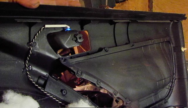
Used one LED for each door handle
Ground - LED - Resistor +12v
Four LED's for driver door switch panel, mounting to the switch frame, this was the hardest part of the project due to limited working space.
Ground - LED-LED-LED-LED - Resistor +12v
- vibe_door_panel_lights2.jpg (14.74 KiB) Viewed 1409 times
Ground - LED-LED - Resistor +12v
- vibe_door_panel_light.jpg (17.44 KiB) Viewed 1409 times
viewtopic.php?f=18&t=42830